Quantcast
Channel: Applied Software
Viewing all 17 articles
Browse latest View live

Plant 3D size editing is a breeze

$
0
0


In AutoCAD Plant 3D 2012, you can change the size of a valve just by going to its properties and making a simple change.


Select the valve, RMC on the valve and select Properties to see the size value.

In Properties, change the size by selecting the drop-down list and choose the new size.

Once the size is changed, close Properties and see the result. There is no need to add reducers to your pipeline. Reducers are automatically added to both sides of the 4" weldneck flanges.

Happy Routing!

Revit Structure to AutoCAD Plant 3D

$
0
0
Scenario: "My structural dept has designed the building and platforms for the plant design in Revit Structure. How do I get them into AutoCAD Plant 3D?"

This is common, especially since the Plant Design Suite Premium and Ultimate comes with Revit Structure. The workflow is simple. My structural model is shown below in Revit Structure 2012. I simply export that file out as a DWG.


Then go to AutoCAD Plant 3D. If you have a drawing started already, in the ribbon, go to the INSERT tab. If you do not have a drawing started, create one. In the REFERENCE section, you will click on ATTACH in order to XRef the drawing into the Plant 3D Drawing. If the coordinates and scale in the Revit Structure model are the same coordinates and scale as in your plant model, then just accept the default insertion and scale.


Your model should now include your Revit Structure design. You can use the geometry on that model for placing equipment and routing pipe just as you would if you had modeled it all with AutoCAD Plant 3D structural shapes.

Happy Routing!

Plant 3D - Rolled Offsets

$
0
0
I have had a few clients ask: "What is the best way to route a Rolled Offset?" As always, there are several methods to this, but here is the one that I feel works best.

First, start with creating or selecting a construction layer or a no-plot layer. This is just a habit of mine and good practice so that you don't get any unwanted lines showing up on your prints.


Next step is selecting the LINE command... (yes, the standard AutoCAD LINE command) and route your line from the nozzle of a tank or where ever you want to route your line from. Be sure to select the NODE of the nozzle so that some magic can happen later.


Continue the LINE command and draw your 3 sides of a rolled offset box (North/South, East/West, and Vertical Directions). In the example below, I drew my line in the North direction 5' then in the + Z direction 3' and then in the East direction 10'. The other grey lines of the box are there to help you visualize the rolled offset. I then used the line command to connet the opposite corners of the rolled offset (see red arrow)


Lastly, use the LINE TO PIPE (_PLANTCONVERTLINETOPIPE) command to change the AutoCAD lines into Pipe. Make sure you have set the size, spec and line number.


Go to the properties of one of the elbows created to see the Cutback Angle automatically assigned.


PLANT 3D 2014 :: Extension 1 - DO NOT INSTALL-To Everyone Until You Test

$
0
0


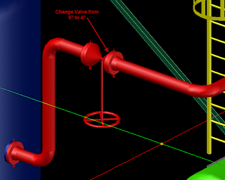
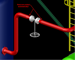
On the Plant Exchange, there is a new (sorta new anyway) Extension that has alot of promise for BOMs in Orthos and Center of Gravity calculations, as well as some Isometric improvements.
http://autocad.autodesk.com/?nd=plant_home

However, upon installing, I started getting errors, crashes, problems problems problems with my Plant 3D.  I tried to uninstall the Extension, but ended up having to completely uninstall and reinstall the Plant 3D.

So, at this time, I would not recommend installing the Extension.  Other links to reference on the Plant 3D Discussion board:


http://forums.autodesk.com/t5/AutoCAD-Plant-3D/Plant-3D-2014-Extension-1/td-p/4349963

UPDATE:
Here is what I have found with my reinstall of Ext 1 on a fresh install of Plant 3D.
REGENALL must be performed on all Orthos and all Isos, what I mean is:  
If i have multiple Orthos open, and toggle between them, I will need to REGENALL.  This will also happen if I have multiple Orthos and Isos open.  When I toggle from an Iso to an Ortho, I must REGENALL.
If I have multiple ISOs open, similar to the Orthos, provided I am looking at the ISOs in model space.  Seem ok if I am viewing the ISOs in PaperSpace.

My original problem that caused me to reinstall P3D in the first place has not come back, which was locking up during Ortho creation.  One note, I definately believe the dialog that says "this may take several minutes" when creating Orthos.  The only thing I can think of that is different is I did uninstall/reinstall .NET Framework 4.5.

Some have reported anomolies in ISO creation, but I am not seeing that.
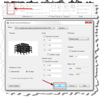
All my orthos have xrefs, and seem to work fine.
Dimscale looks good.
Properties Palette good.
All my tests were with existing projects.
I tested on another PC that had only Plant Design Suite, no other suites installed.  Same issue with REGENALL, but none of the others problems people have reported.

So, at this time, for me, I think I will put up with having to REGENALL in exchange for the added functions/capability of the Ext 1.  

I recommend that in any given environment, that one person on the Plant team install the Extension and do some detailed testing before everyone on your team installs it.

And I do request any feedback from others on this issue.  I do believe the Plant Team at Autodesk is always pursuing quality with this product and will be attentative to all issues.


Odds and Ends – A variety of things I have found for 2015

$
0
0

While I have had good experiences over all with the Autodesk 2015 products, as with any software there were fixes along the way.  Here are my discoveries of some of those obscure and maybe not so obscure.

    
    1)  AutoCAD 2015 Cursor trails:  Moving your cursor along would leave pixels everywhere.  Turning off Hardware Acceleration would clear up the problem.  Install the Service Pack and you can turn Hardware Acceleration back on.


2)      Plant 3D 2015 Extension 1: The Plant developers are not waiting on new releases to give more functions in P3D.  However, the Extension 1 was not compatible with AutoCAD Service Pack 2.  You cannot even install the SP2 for a particular vertical, such as AutoCAD MEP, without it affecting P3D.  But, there is a fix that fixes the fix that broke the Extension 1.  After installing any AutoCAD 2015 SP2, run the .BAT file.


      3)      AutoCAD Electrical 2015: The error could come with several messages.  The main one I have seen is:  Unhandled Exception C06D007E(Delayload “acewstr.dll” Module Not Found) at address FCFA940Dh.  Just running a Repair or Reinstall will not help.  The fix is to uninstall the Microsoft Access database engine 2010 and reinstall from the install path, and may be a variation depending on install method:

…\...\Autodesk AutoCAD Electrical 2015\3rdParty\AceDataEngine\x64\AceRedist.msi.


4)      Recap 2015: Will not open a .FLS file format:  While the File of Type shows it, an error will keep coming up that says it isn’t a supported file type or is corrupted.  You will need to install the Faro Scene 5.3 SDKs and register new DLLs.  This is done all manually, in that there is no MSI to run to fix it up.


    5)      Multiple Suites Install:  Most of you probably will not run into this, but in my world it is standard business to need to install multiple suites.  If Factory Design Suite is one of yours, install it first.  When you install it, the Application Manager will want to update a lot of the applications.  Don’t do it until you are finished with the other suites.  I have found that, for example, reinstalling a suite or the subsequent suite install will want to install the BIM360.  But if it is already upgraded, the install will message that a newer version is already installed and then close out, without installing the applications needed.  The fix if this happens, is to go back and uninstall all the BIM360s.

dennis

AutoCAD Plant 3D and Vault

$
0
0
Stop using Bentley's ProjectWise or any other data management solution for managing AutoCAD Plant 3D projects.  They do not work!  There is little to no integration at all.

"What will work?"  Autodesk Vault Professional!

Applied Software is well-versed in the integration of Vault and AutoCAD Plant 3D and you need to make the switch today!

"How does this benefit me?"

◾Check in and out drawings

◾Utilize a horizontal workshare environment with multiple locations utilizing Vault Professional and AVFS (Autodesk Vault File Server)

◾Work locally from your Vault Workspace so you do not have to rely on poor network speeds when saving large models

◾Revision control

◾Permission control


The benefits are there so take advantage of them now!

Easy Python Decompiler

$
0
0

This post is for CAD Managers for Plant 3D!  I found a great decompiler for Python the other day.  It is called Easy Python Decompiler and i found it on SourceForge.  If you want to get into the Variants.ZIP file and see how all of these 3D solids in Plant are created and attempt to create your own, try it out!

You can download it here:  https://sourceforge.net/projects/easypythondecompiler/files/bin/


Converting Plant 3D projects to Vault projects

$
0
0

You have created your project(s) and have been working for months or years in Plant 3D.  The IT director comes in and says, "We are going to Vault Professional!"  As a designer, you may be thinking sarcastically, "Oh great, something else to learn..." or you may be thinking, "We need something like this to help secure our projects and make horizontal workshare a real possibility!"  You would be right on both thoughts.  There are many advantages to making the move to Vault Professional in regards to AutoCAD Plant 3D, and we can help you explore those benefits.  But you more than likely will have several projects you are already working on that will need to be moved to this new Vault.  It is really an easy task and here are the steps.


In Plant 3D, open the project you want to convert.  Do not open any of the drawings.  From the command line, type in PLANTPROJECTTOVAULT.  You will see the following dialog box asking you to enter in Vault and SQL information.


 After selecting "Start" you will see the following dialog box indicating the process is underway.  Just sit back a few minutes and let it run.


Once completed, you will be able to check in and out drawings from the project with the appropriate credentials set up in Vault.  If you are curious about how Vault and Plant 3D work together, please do not hesitate to contact us for a discovery call.  There is an explicit methodology of working with Plant 3D and Vault concurrently so be sure to reach out to us.


Complex Routing in AutoCAD Plant 3D - #1

$
0
0

From time to time, you will come across a pipe route that just stumps you.  This one came up today with a user and this was the solution to the route.  If you know a better way, please comment and let us know and make us all better pipe designers

The scenario was two vertical pipes coming off of a tank.  One pipe would turn right at a higher elevation than the second pipe.  The second pipe would turn at 45 degrees and tee into the bottom of the first pipe's horizontal run.

Hopefully you can visualize the route from the images above.  Here are the steps using some constructions lines, the TRIM command and LINE-TO-PIPE.

1.  Erase the horizontal pipe on the higher elevation run.

2.  Draw 2 construction lines:  1 replacing the horizontal pipe you just erased and 1 at 45 degrees horizontal off of the elbow.  Make sure the line crosses over the 1st construction line in the plan view.

3.  Once drawn, you will want to TRIM the 2nd line using the TRIM command.  However, this is not a standard trim in that you will trim based on PROJECTed geometry so the syntax will look like this:

4.  Now just draw a new LINE from the endpoint of the trimmed LINE and perpendicular to the 1st LINE:

5.  Lastly, a LINE TO PIPE command from the Ribbon (PLANTCONVERTLINETOPIPE) will convert those LINEs to Pipe by selecting them with a crossing window or selecting them one at a time...

and your complex pipe route is complete!  Again, if you know of a better way, comment and make us all smarter!

More complex routing to come!  I will also be teaching this and other "Tricks of the Trade" at Autodesk University this year! 
Look it up and sign up - PT21675  Plant 3D: Tricks of the Trade 2.0  
http://au.autodesk.com/

Complex Routing in AutoCAD Plant 3D - #2

$
0
0
Resting Pipe on Steel Members or other objects can be difficult unless you know the tricks.  

Here is the scenario:  
Horizontal route needs to turn down vertically and then needs to turn horizontally to lie across steel.

To route this pipe, you will want to continue the pipe run by selecting the pipe and then the + at the
end of it.  You will pull down seeing an elbow in the route.


You will need to set the routing line to BOP.  You will find this in the ribbon (Home tab, Routing &
Elevation panel)


Use the .X point filter to select the top of steel that you want the pipe to lie across

Select the Steel member’s top edge and notice that the pipe will not travel past the steel when you pull in that direction.  Make sure your Ortho (F8) is turned on.  You will also notice that the red line should be on the BOP and not on the COP.


Change your PLANE (compass) to a horizontal configuration to get the pipe to lie across the steel.
If it is not changed, the COP will still be on the TOS.  When you pull in the direction of the steel, you
will see the pipe lying on the TOS.

Lastly, pick or enter the length of the pipe you desire and see the results.   Your BOP should be the 
same as the TOS and you were able to do this without knowing the TOS elevation


More complex routing to come!  I will also be teaching this and other "Tricks of the Trade" at
Autodesk University this year!
Look it up and sign up - PT21675  Plant 3D: Tricks of the Trade 2.0 
http://au.autodesk.com/


Hey Plant 3D Users - Autodesk University is near!

$
0
0

Attention all Plant 3D Users!

This year Autodesk University has been moved to the week before Thanksgiving instead of the week after.  Mark your calendars for the November 15-17!

Registration for AU opened August 17!  You will want to register early to ensure that the classes you want are not filled up.  As you register make sure you check out the class I will be teaching.   As you can see, as of today, it is down to 23 seats remaining so sign up before they are all gone!

See you in Vegas!


AutoCAD Plant 3D Structural Editing - "Cut Member Edges"

$
0
0

The little icon that probably does not get used very often is actually a very nice tool for automatically cutting back members to include a gap if required.  See the image below of the structural members.  They were placed on a grid on center, which will require some clean up.  The grid has been turned off for clarity.


We need to trim the members back and to do this quickly, we will use this tool as seen in the next image.

So as the instructions indicate, this tool will cut multiple members back to the edge of a member that is placed on endpoints of the adjacent members.  After selecting the command, it will prompt you to enter in a "gap", which can be just zero or can be a gap that you specify.  This will leave a gap between the end of the member and the face of the cutting member.

Select the members you wish to cut back.  In the example below, I just used a crossing window to select them all at once.


After selecting the members you need to cut back, hit ENTER and see the work done for you!  This is much better than doing one at a time.


Experiment with this tool to see how you can add gaps in the cut and look for circumstances that it does not work for, because there are some of those too.

AutoCAD Plant 3D Tricks of the Trade 2

$
0
0

You can now view the class "AutoCAD Plant 3D: Tricks of the Trade 2" from this year's Autodesk University.  You will learn such things as...

  • Complex pipe routing tricks
  • Structures and platform creation tricks
  • Equipment creation tricks
  • Support placing tricks
  • and BONUS Tricks

Click here >> AutoCAD Plant 3D: Tricks of the Trade 2

AutoCAD Plant 3D - Sloped Socketweld Piping

$
0
0

Have you ever experienced the issue of your vertical pipe in a sloped socketweld pipe run not being truly vertical?  This screencast will help!

Sloped Socketweld Piping

Clevis Hanger with Rod and Scissor Clamps and Toggle Lock Point of Support

$
0
0
Click this Screencast to see how to place a Clevis Hanger on a pipe, adjust the scissor clamps to the overhead beam, and copy that hanger to another elevation while maintaining the beam elevation for the scissor clamp.

Combining Disciplines: Factory Design and Plant 3D

$
0
0
 Click this Screencast to see how to insert a Factory Design Assembly into an AutoCAD Plant 3D model.

AutoCAD Plant 3D 2018 - Cloud Collaboration is here!

$
0
0


New Features in Plant 3D

If you have been in the loop with AutoCAD Plant 3D over the past year, you have probably heard of Project Calgary which was the beta of Collaboration of Plant 3D Projects in the Cloud.  Why is this an important feature for AutoCAD Plant 3D?  It centralizes your project for multiple sites and still allows you to work locally as if you were on Vault.  Look at it like using Vault in the Cloud, because that is precisely what it is! 

How does this work?  Today, I created a new project, local using SQLite.  I called it "Cloud Project Demo." I did not reference any other projects.  I just wanted to start from ground zero and go from there.  I created one P&ID drawing in the project called 1001.DWG.  Upon creating the first DWG, I was able to go to the new "Collaboration" tab in the ribbon and selected "SHARE PROJECT" after which I was shown the following dialog box:

Pretty simple so far!  After selecting "GET STARTED!" you will be prompted to close any DWG you have open in the project if you left one or more open and then you will be prompted to select a BIM 360 Team project folder you have already created.  If you haven't created one, you will need to do that first.  By the way, the ribbon option to "Share Project" will not highlight unless you have a drawing open.  Also, I have found that if you upload to Fusion 360, the projects will not be seen by your team.  Make sure it is a BIM 360 Team Hub.


After selecting the folder, sit back a minute or 2 and let the project upload to the cloud...

Next, you need to determine who is going to work on this project with you.  It is collaboration, after all.  

After the "INVITE MY TEAM" takes you to the site, invite your Project team by entering in their email address.

Back in AutoCAD Plant 3D 2018, you can go to the Project Manager, right-click on a drawing and see the new "Project Collaboration" commands, such as Check Out.

If you have used AutoCAD Plant 3D with Vault in the past few releases, you will quickly start to see some of the familiar icons for files checked out to you and files checked out by others.  You can even set it up to notify you by email when DWGs have been updated by others.

Give it a whirl!  This is good stuff and highly requested technology!  Kudos to the Autodesk Plant Development Team!


Viewing all 17 articles
Browse latest View live


Latest Images